Slavnostní zahájení významného investičního projektu – „Kalové hospodářství ČOV Brno – Modřice“

Šance Dam - extreme flood wave transfer
Project title: Šance Dam - extreme flood wave passage
Investor: Povodí Odry, státní podnik
Contractor: OHL ŽS, a.s.
Design engineer: AQUATIS a.s.
Time for completion: 08/2015 to 10/2018
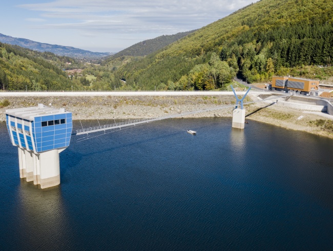
Basic data: The Šance Dam is located in the Moravian-Silesian Region, in the district of Frýdek – Místek, in the cadastral district of the municipalities of Ostravice and Staré Hamry, on the Ostravica river, the dam is situated in river km 45,770. It is a rock-fill dam (the dam was completed in 1969), at its time it was the highest in the Czech Republic, the total volume of the reservoir is approx. 62 million m3, the basic purpose of the reservoir is to serve as an extremely important source of drinking water for the Moravian-Silesian region and it also has a flood control function. The reservoir is located in the beautiful natural environment of the Beskydy Mountains.
Reasons for reconstruction: Requirement for safe passage of control ten-thousand-year flood PV10,000.
The main reasons for reconstructing the Šance dam are as follows:
• Changed hydrological documentation, changes were already made before the end of the Šance dam construction and repeatedly during its operation;
• Changes in standards concerning the assessment of dam safety during floods
• Comprehensive reconstruction of the dam after more than 40 years of operation.
Scope of the reconstruction in a nutshell:
The project mainly addresses a substantial increase in the capacity of the spillways and chute spillways of the Šance dam (category I) by rebuilding the original safety systems - spillway, chute spillway and stilling basins and the connecting channel, a set of measures aimed to increase the dam stability and the possibility of raising the maximum permissible safe water level, reconstruction of the dam crest, subsoil sealing, drainage, TBD measurement system incl. instrumentation and data transmission, construction of a new operation center, set of utility networks, roads, bridging, modifications and other related measures and construction work related to the complete reconstruction of the dam.
Important information:
• The construction was carried out with the dam in operation,
• for the duration of the reconstruction, safety of the dam was ensured at a min. of PV1000,
• for the duration of the reconstruction, the supply of raw water to the treatment plant in Nová Ves was ensured in the required volume of 0.90 m3/s.
Basic spillway and chute spillway parameters
SO 11.1 Spillway - apron
Technical parametres
Spillway capacity at the maximum permissible safe water level of 507.91 m a.s.l. 390 m3 s-1
(390 m3/s is the transformed flow rate of Q10,000)
Length of the spillway crest with the crown elevation at 504.20 m a.s.l. (in the axis of spillway crest) 12.90 m
Length of the spillway crest with the crown elevation at 505.90 m a.s.l. (in the axis of spillway crest) 35.70 m
Length of the apron approx. 47.50 m
Width of the apron at the bottom approx. 15.90 m
longitudinal slope of the apron bottom in the axis 2%
stilling basin depth 7.40 to 8.50 m
Demolition of concrete structures approx. 700 m3
Concrete C30/37, XF3, S4, 90d (specifications according to the contractor) approx. 4,100 m3
SO 12 Chute spillway
Technical parametres
Length of the chute spillway in the axis approx. 185 m
Width of the stilling basin at the bottom approx. 13.00 m
Maximum chute spillway width at the bottom (gradual change in width from 13 m in the direction of the spillway) 15.90 m
Longitudinal slope of the chute spillway bottom from the top 2.0%; 27.3%; 45.0% and 6.0%
Highest/ lowest elevation of the chute bottom (baffle) approx. 500.0/449.13 m a.s.l. Bpv
Excavation and breaking approx. 13,100 m3
Demolition of concrete structures approx. 3,600 m3
Screeding concrete and concrete filler approx. 2,950 m2
Concrete C30/37, XF3, S4, 90d (specifications according to the contractor) approx. 5,100 m3
Work provided by AQT
• Feasibility study - 2006.
• Zoning permit, building permit documentation, tendering documentation and detail design - 2007 to 2009.
• Detail design update - 2013.
• Designer’s supervision during implementation - 2015 to 2018.
• As-built documentation- 2018
