Slavnostní zahájení významného investičního projektu – „Kalové hospodářství ČOV Brno – Modřice“
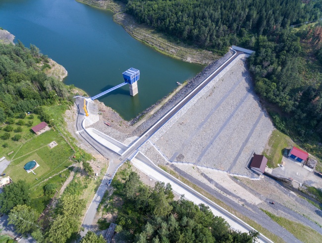
Opatovice Dam - reconstruction of the dam
Investor: Povodí Vltavy, státní podnik
The main objective was to increase the capacity of the spillway, bridging the chute and spillway chute (SO 02, SO 03 and SO 04). The proposed technical solution indicated that the original location of the structures was preserved but there was a significant change in the dimensions of the safety spillway and the width of the spillway chute was increased. The changed chute spillway parameters were related to the expansion of the stilling basin (SO 05). The increase in dimensions resulted from the requirements for increased capacity. Although there was an increase in the dimensions of concrete civil structures, their design was based on the effort to integrate the structures into the existing terrain morphology in the least possible disturbing manner. The design of partial structures (chute wall ledges, stairs along the chute spillway, spillway crest) contributed to a more favourable appearance of the structures. Expansion of the stilling basin and waste channel does not deteriorate the visual appearance of the structure.
Civil structure SO-01 top of the dam concerned intensification of the dam core, construction of a new breakwater, construction of movable gates next to the emergency spillway, and sealing of the space behind the retaining wall on the left side of the dam attachment into banks.
Civil structure SO-08 Toe weight addressed the raising of the downstream face of the earth dam, construction of a retaining wall made of wire stone mattresses necessary to support the foot of the fill behind the machine room of the bottom outlets, construction of a drainage system at the foot of the fill including an underground sealing wall and construction of a new staircase on the right side of the downstream face of the dam - in the space between the toe weight and the chute spillway.
Parameters:
SO 02 Safety spillway
Total length of the apron at the bottom is 30.24 m
Spillway edge length: 32.80 m
Apron width 6.0 m
SO 04 Chute spillway
Total length of the chute spillway 131.47 m
Width of the transition block at the bottom 6.00 m
Width of the part connecting to the stilling basin 4.00 m
Longitudinal slope of the chute spillway 15.62% / 54.02 m, 27.27% / 42.31 m
Radius of the circular arc of the grade line 50.0; 100.0 m
Wall height above Q10000 in a length of approx. 50.0 m below the chute spillway bridging 0.60 m
Wall height above Q10000 in the remaining part 0.30 m
Chute spillway depth 3.20 m
Chute depth at the inlet to the stilling basin 6.87 m
SO 05 Stilling basin
Total length of the stilling basin 29.93 m
Width at the front of the stilling basin 4.60 m
Width at the end of the stilling basin 7.65 m
Stilling basin bottom grade line 291.73 m a.s.l.
Stilling basin crest wall level 298.60 m a.s.l.
Stilling basin end sill level (original bed) 296.15 m a.s.l.
Length of the fortification downstream the stilling basin sill 20.0 m
SO 08 Toe weight
Toe weight width 1x 3.0 m and 2x 2.0 m
Toe weight elevation 326.00 m a.s.l., 319.50 m a.s.l. and 309.50 m a.s.l.
Stone packing elevation 333.00 m a.s.l.
Route composition - slope between toe weights 1: 1,4, 1 : 1,5 a 1, : 1.65
Toe weight length at the bottom of the slope is 60 m
Toe weight length at the level of the upper toe weight 158 m
Toe weight height (relative to the lowest level of ZS 297.10 m a.s.l.)
Work provided by AQUATIS:
Building permit documentation
Detail design
Designer's supervision
We would love for you to connect with us
Contact informationAQUATIS is part of the SAFICHEM GROUP. A team of experienced specialists, state-of-the-art working tools and thousands of completed projects are a guarantee for the realization of top projects both at home and abroad.
Navigation
News
Contacts
-
- Address
- Botanická 834/56, 602 00 Brno
-
- Mobile
-
- info@aquatis.cz